- 您现在的位置:买卖IC网 > Sheet目录321 > DM300018 (Microchip Technology)BOARD DEMO DSPICDEM 2
�� �
�
�Getting� Started�
�2.5�
�DEVICE� PROGRAMMING� PROCESS�
�The� second� phase� of� the� getting-started� process� introduces� the� MPLAB� Integrated�
�Development� Environment� (IDE)� and� MPLAB� ICD� 2� In-Circuit� Debugger.� The�
�emphasis� in� this� phase� is� to� program� the� sample� application� into� a� dsPIC30F4011�
�device.� After� observing� the� demonstration,� this� process� gets� you� ready� to� examine�
�what� you� observed.�
�2.5.1�
�Connect� MPLAB� ICD� 2�
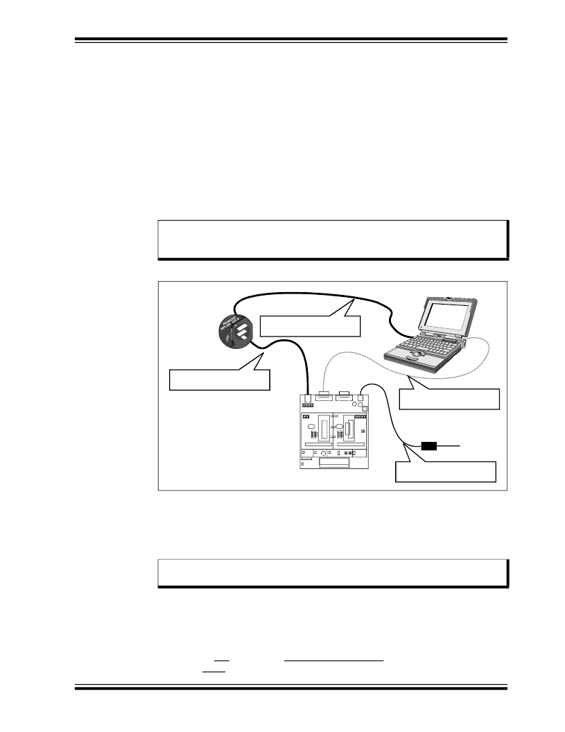
�Follow� the� information� in� Figure� 2-2� to� set� up� the� MPLAB� ICD� 2� for� use� as� a�
�programmer.�
�1.� With� an� RJ11� cable,� connect� the� MPLAB� ICD� 2� to� the� ICD� header� (J1)� on� the�
�board.�
�2.� Use� a� USB� cable� to� connect� the� MPLAB� ICD� 2� to� your� PC.�
�Note:�
�Make� sure� that� the� USB� driver� for� the� MPLAB� ICD� 2� has� been� installed� on�
�your� PC� (see� the� MPLAB� ?� ICD� 2� User� ’s� Guide,� DS51331,� for� more� details�
�regarding� the� installation� of� MPLAB� ICD� 2).�
�FIGURE� 2-4:�
�MPLAB� ?� ICD� 2� CONNECTION� DIAGRAM�
�PC� running� MPLAB� ?� IDE�
�MPLAB� ICD� 2�
�Connect� USB� cable� to� PC�
�Connect� RJ-11� cable� to� ICD�
�J1�
�J2�
�J4�
�Connect� RS-232� cable� to�
�1� 2� 3� 4�
�1� 2�
�J2�
�U2A1�
�U2B1�
�J3�
�U1A1�
�U1B1�
�1� 2� 3� 4�
�PC�
�dsPICDEM?� 2� Development� Board�
�running� dsPIC30F4011� sample�
�H8�
�Motor�
�Control�
�H9�
�General�
�Purpose�
�U1C1�
�9� VDC� Power� Cable�
�115� VAC�
�application�
�Apply� power� to� the� board�
�2.5.2�
�Setting� up� MPLAB� IDE�
�The� sample� application� program� files� on� the� dsPICDEM� 2� CD� contain� a� workspace� and�
�project� information� needed� by� MPLAB� IDE,� MPLAB� ICD� 2� and� MPLAB� C30.�
�The� first� step� is� to� open� the� sample� application� project� in� MPLAB� IDE.�
�Note:�
�These� instructions� presume� the� use� of� MPLAB� IDE� version� 7.11� or� newer�
�and� MPLAB� C30� version� 1.32� or� newer.�
�A� project� contains� the� files� needed� to� build� an� application� (source� code,� linker� script�
�files,� etc.)� along� with� their� associations� to� various� build� tools� and� build� options.� A� work-�
�space� contains� information� on� the� selected� device,� debug� tool� and/or� programmer,�
�open� windows� and� their� location,� and� other� MPLAB� IDE� configuration� settings.�
�1.� Start� MPLAB� IDE.�
��where� [path]� is� the� location� of� the� sample� application� files.�
�?� 2005� Microchip� Technology� Inc.�
�DS51558A-page� 17�
�发布紧急采购,3分钟左右您将得到回复。
相关PDF资料
DM300019
BOARD DEMO DSPICDEM 80L STARTER
DM300024
KIT DEMO DSPICDEM 1.1
DM330012
KIT USB STARTER FOR DSPIC33E
DM330013
MICROSTICK DSPIC33F/PIC24H BOARD
DNET1
SURGE SUPPRESSOR ETHERNET RJ45
DR-8094
RACK DOUBLE 84"X20.25"X36" BLK
DR-IAC5E
INPUT MODULE AC 5VDC
DRIDC24A
INPUT MODULE DC 34MA 24VDC
相关代理商/技术参数
DM300018
制造商:Microchip Technology Inc 功能描述:DEMO BOARD ((NW))
DM300019
功能描述:开发板和工具包 - PIC / DSPIC dsPICDEM 80L Starter Demo Board RoHS:否 制造商:Microchip Technology 产品:Starter Kits 工具用于评估:chipKIT 核心:Uno32 接口类型: 工作电源电压:
DM300019
制造商:Microchip Technology Inc 功能描述:DEMO BOARD STARTER ((NW))
DM300020
功能描述:开发板和工具包 - PIC / DSPIC dsPICDEM MC1 Motor C RoHS:否 制造商:Microchip Technology 产品:Starter Kits 工具用于评估:chipKIT 核心:Uno32 接口类型: 工作电源电压:
DM300021
功能描述:开发板和工具包 - PIC / DSPIC High V Pwr Module RoHS:否 制造商:Microchip Technology 产品:Starter Kits 工具用于评估:chipKIT 核心:Uno32 接口类型: 工作电源电压:
DM300021
制造商:Microchip Technology Inc 功能描述:MODULE dsPICDEM MC1H 3 PHASE
DM300022
功能描述:开发板和工具包 - PIC / DSPIC Low V Pwr Module RoHS:否 制造商:Microchip Technology 产品:Starter Kits 工具用于评估:chipKIT 核心:Uno32 接口类型: 工作电源电压:
DM300023
功能描述:开发板和工具包 - PIC / DSPIC dsPICDEM SMPS Buck Demo Brd RoHS:否 制造商:Microchip Technology 产品:Starter Kits 工具用于评估:chipKIT 核心:Uno32 接口类型: 工作电源电压: